
Com-Power ISN-T2 ISN, 150 kHz to 30 MHz, Cat. 3 or Cat. 5 Cabled Networks
Our Part #:N|COP|10136
Condition:New
Mfr Part #:ISN-T2
Com-Power ISN-T2 ISN, 150 kHz to 30 MHz, Cat. 3 or Cat. 5 Cabled Networks
Our Part #:N|COP|10136
Condition:New
Mfr Part #:ISN-T2
- Description
- Specifications
- Documents
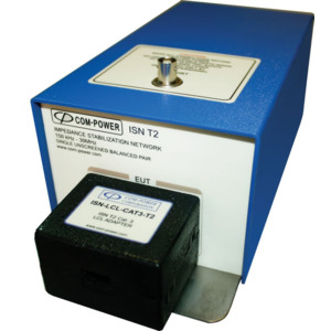
The Com-Power ISN-T2 is used for common-mode disturbance voltage measurements on ports with a single, unshielded, balanced pair for Cat. 3 or Cat. 5 cabled networks. The RF input/output port is a 50Ω female BNC connector, located on the top of the ISN. The ISN is equipped with D-sub 25 pin female connectors located on the front and rear panels for connection to the LCL and connecting adaptor, respectively. The LCL and connecting adaptors are available with either RJ11 or RJ-45 connectors for connection to the EUT and AE. For non-standard pin arrangements, the ISN can also supplied with user-configurable LCL and connecting adaptors which can be configured for any pin arrangement.
The ISN and LCL adaptors are individually tuned and calibrated to meet the applicable requirements of EN 55022 (CISPR 22) and CISPR 16-1-2. The calibration data and certificate are provided, with NIST traceability. Recognised ISO 17025 accredited calibration is also available upon request.
ISN Concept & Advantages
The ISN (Impedance Stabilisation Network) was developed in order to provide a means by which common mode disturbance voltage (a.k.a.: conducted emission) measurements could be made on unshielded, balanced telecommunication ports with up to four, unshielded, balanced pairs.
The basic concept of the ISN is similar to that of an LISN (Line Impedance Stabilisation Network) for disturbance voltage measurements on power lines, insofar as they both:
- Connect in series with, and impose a defined impedance on, the lines under test; thereby providing a distinct advantage over current or voltage probe measurements, where the impedance of the lines is largely uncontrolled.
- provide isolation between the input and output ports, which:
• Minimises the influence of the [unknown] input impedance on the impedance of the network.
• Reduces the contribution of unwanted [ambient] signals to the measurement results.
The ISN is used for measurements on lines which host various types of high-speed, symmetric (differential-mode) communications, often operating within the same frequency band over which the measurements are performed. It is for this reason that, from a differential-mode perspective, the ISN should not impede the wanted signal path [thru-put], but should impede the path to the measurement port, as the intent of the test is not to limit the level of the wanted signals. In addition, the ISN measures all conductors of the line simultaneously with respect to ground, thereby measuring only the common-mode voltages, and not the differential.
In contrast, the LISN is used to measure each current carrying conductor individually, with reference to ground, making no distinction between, and therefore measuring, both differential and common mode voltages. In most cases, it need only pass the power frequencies (50 or 60 Hz), far below those frequencies over which measurements are performed.