
Com-Power ISN-T8 ISN, 150 kHz to 30 MHz, Unshielded Telecom Lines, 1 to 4 Balanced Pairs
Our Part #:N|COP|10137
Condition:New
Mfr Part #:ISN-T8
Com-Power ISN-T8 ISN, 150 kHz to 30 MHz, Unshielded Telecom Lines, 1 to 4 Balanced Pairs
Our Part #:N|COP|10137
Condition:New
Mfr Part #:ISN-T8
- Description
- Specifications
- Documents
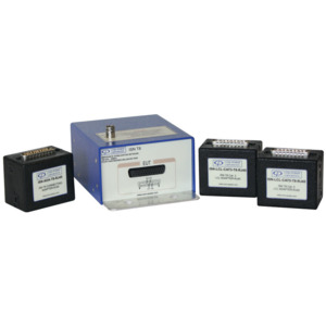
The RF Port is a 50Ω female BNC connector, located on the top of the ISN. The ISN is equipped with two D-sub 25 pin female connectors located on the front panel (EUT Port) and rear panel (AE Port), providing the interface to the LCL Adaptor and Connecting Adaptor, respectively. The Cat. 3 and Cat. 5 LCL adaptors are tuned to provide the appropriate Longitudinal Conversion Loss (LCL) for the given cable categories, and also provide the interface to the Equipment Under Test (EUT). The Connecting Adaptor provides the interface to the AE.
Adaptor sets include one Cat. 3 and one Cat. 5 LCL Adaptor, along with one Connecting Adaptor. The ISN-T8 is provided with an adaptor set equipped with RJ45 receptacles wired per ANSI/TIA/EIA-568-B. Adaptor sets are also available with 4-pin RJ11 receptacles. For non-standard arrangements, adaptor sets are also available with (8) 1mm banana jacks. This set also includes two RJ45 (or RJ11) to 1mm banana plug wiring adaptors, allowing the user to adapt to virtually any pin/ wiring arrangement.
ISN Concept & Advantages
The ISN-T8 Impedance Stabilisation Network provides a means by which common mode disturbance voltages (conducted emissions) can be made on unshielded, balanced telecommunication ports with up to four, unshielded, balanced pairs.
The concept of the ISN is similar to that of the LISN, (used on power lines), insofar as they both:
- Connection series with, and impose a defined impedance on, the lines under test; thereby providing a distinct advantage over current or voltage probe measurements, where the impedance of the lines is largely uncontrolled;
- Provide a coaxial RF measurement port for connection to the measurement equipment, to which the disturbance voltages present at the EUT port are coupled for measurement; and,
- Isolate the AE (ancillary equipment) port from the EUT and RF ports, which:
• Minimises the influence of the AE-connected equipment/ cabling on the impedance (and voltage division factor) of the network; and,
• Reduces the amplitude of any ambient signals, as well as spurious disturbance voltages generated by the AE-connected equipment, thereby minimising their potential impact on the measurement results.
The main difference between an ISN and an LISN is the coupling method utilised. Most LISNs are used to measure each current-carrying conductor separately, with reference to ground. Consequently, both differential and common mode voltages are measured.
ISNs are used on telecommunication lines hosting high speed, symmetric (differential-mode) communications, often operating at frequencies within the measurement range. As the intent of the test is to limit only the spurious voltages, the ISN measures all conductors of the line simultaneously with respect to ground, thereby measuring only the common-mode disturbance voltages, while effectively ignoring the intended, symmetrical (differential) voltages.